- Influence of operator and print medium eliminated
- Four times faster test than regular PCA test (around 1 hour)
- Accuracy and force measuring with one device
- Measurements during printing
- Theta is measured
- Best possible calibration on all type/model of printer
- All problems can be easily identified and fixed

CmPrint 2.0 Expert: Accuracy, stability and Force measurement for printers
CmPrint 2.0 Expert
CeTaQ's CmPrint 2.0 Expert is an improved version of the basic system. This measuring system is designed to investigate simultaneously the accuracy, stability and squeegee forces during the printing process. The machine capability test is performed dynamically over the entire squeegee stroke without using any print medium (glue or solder paste) and operator influences. This new type of measurement provides many valuable information on accuracy (Offsets in x-, y-, and theta-direction), stability (repeatability of the printing process) and force (applied pressure and its behavior over the printing area).
As the first process step in SMT production, solder paste printing is of particular importance. Its quality has a decisive influence on all subsequent process steps. Printing offsets between the printing directions are usually adjusted with machine calibration (using supplier tools) or using external measurement system (3DAOI or human inspection). In both cases, the accuracy of these tools is strongly influenced by the process, the operator and the measurement tools themselves.
Moreover, some characteristics are not considered (no Force or Theta for example). With CmPrint 2.0 Expert, this state of the art measurement tool delivers a complete and unique diagnose of the machine accuracy/force with most relevant characteristics on any type and brand of equipment. This allows necessary maintenance, repair or optimization measures to be carried out in a targeted manner.
Furthermore, the knowledge gained facilitates the planning of new products, the introduction of new technologies and helps with investment decisions.
New experiences, findings and requirements from our measuring service form a basis for continuous further development. Our wealth of experience from the measurement of thousands of systems helps you to fulfill your measurement tasks efficiently.
A frequent task for our measuring service is the verification of the position accuracy of printed depots.
The following phenomenon often appears during the measurements. Several printers of the same type with the same material, board, stencil, squeegee and paste, are measured one after the other. For an optimum print quality, however, the print parameters such as x-y offsets, stability and squeegee force must be accurately adjusted on all machines. The experience we have gained during testing is in line with observations of our customers from real production. If a functioning product is shifted to another line, or even to an identical line, adjustments in the machine parameters may become necessary. This indicates that these printers differ in their machine settings and quality level.
Against this background, the demand arose to create a measuring device with CmPrint 2.0 Expert that allows a quick and easy evaluation/calibration of all the relevant characteristics for a printer. All the machines of the production lines are controlled, improved and calibrated with the same dedicated measurement device.
A measurement with CmPrint 2.0 Expert allows statements on Accuracy (Offsets in x-, y-, and theta-direction), stability (repeatability of the printing process) and Force (applied pressure and its behavior over the printing area). For more detailed information about force measurement, please refer to CmPrint 2.0 Basic.

Firstly, global offsets in x-, y-, and theta-direction are measured and adjusted like measurements with printed deposits. Systematic global offsets for each print direction are determined accurately with the device and will be modified in the printer machine settings. These adjustments can be compared to a highly accurate calibration.
Secondly, the possibility to measure the angle for each print (Theta) provides way better accuracy, especially for larger PCB. For example, With a PCB size of 205 x 187mm, a twist of 0.01 degrees causes an offset of 18 microns in x-direction and 16 microns in y-direction on all the corners of the board.
Thirdly, the special feature of the CmPrint2.0 Expert system is that the measurements are performed during the printing process with optionally the squeegee force. Any movement between the board and the stencil can be immediately detected. It appears that printers with poorer print quality (appearance of printed deposits), have greater movement between board and stencil. The chart below shows the evolution of the printing offsets as the squeegees force progressively increases every 10 prints. In the upper graph, the offsets increase significantly and proportionally to the applied force. The main identified problems are : Tilting of the table, which caused a movement between PCB and stencil. Instabilities in the angle offset and poor print image (wet print). In the graph below (a good printer), the offsets increase much less.


Finally, independently of the global offsets present on all screen printing machines and adjusted in the machine parameters, the Cmprint 2.0 Expert repeatedly measures the offsets during each squeegee cycle. This allows us to test if the table does not move during the printing process. Movements between board and stencil can cause a poor shape quality of printed deposits.
In the following chart, the position of the stencil aperture was measured every two seconds four times in total during one print. In this example a movement of approximately 32 microns during printing can be determined in y-direction. The cause is usually a movement of the printing table during printing.

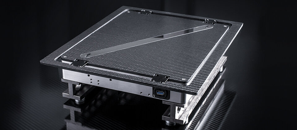
Sensor board equipped with measuring plate
The central component of the measuring system is a sensor board with a rectangular measuring area of 300 x 250 mm. This is fixed on the printing table of the printer to be measured. There are different support heights depending on the type of printer. The necessary measuring electronics is connected to the sensors via a USB cable. Forces acting on the sensor surface are recorded and analysed by the CmForce software.
The sensor board allows the measurement of all common paste printers and works completely independent from the manufacturer.
CmPrint 2.0 Software
The corresponding software CmPrint 2.0 analyses and saves the measurement results using CmCvis2.0. The most important features are:
- Database Management of machines, lines and user database
- Statistical evaluations and calculation of capability results
- Analysis of the results over several prints with graphics
- Separation and comparison of the two squeegee directions (forward and reverse)
- Edit PDF report with all results
- Data export for CmCStat6 and QSStat
Procedure of a measurement
Before the first measurement a corresponding print program must be available or newly created. We recommend at least 25 measurements for each squeegee direction. The required measuring time is essentially equal to the time the printer needs for processing. After finishing the measurement, the data is analyzed directly. For example, deviations from the set target value, differences between the printing directions or inconsistencies in the force or accuracy distribution can be detected. It is recommended to repeat the measurements with the settings used in production. At the end of the analysis, a report can be generated with one click and thus the condition of the equipment can be documented.
Customers who own a CmController with CmCStat6.0 Expert also have the possibility to export the data and analyze, document and archive them in CmCStat6.0.
Added value between glue dots measurement and Cmprint2.0 expert
The measurement accuracy is examined using a calibrated reference measuring plate. The system meets the requirements specified there with regard to measuring instrument capability and reproducibility for the following process limits to be verified.
Technical Specifications :
- Measuring area of the sensor board: 300 x 250 mm
- Height: depending on the printing height of the printer