- Specialized in SMT requirements
- Measurements directly in the production
- Evaluation optimized for finding causes of errors
- Quick and detailed documentation of the results
- Competent and well acquainted consultation with the measuring tasks due to extensive experience from our measurement service.
- Simple answer to the familiar question, "How do you make sure ...?"

CmPrint 2.0 Basic: Dynamic measurement of squeegee forces
CmPrint 2.0 Basic
The CeTaQ CmPrint 2.0 Basic measuring system is designed to investigate the progression of squeegee force during solder paste printing. The measurement is performed dynamically during the printing process over the entire squeegee stroke. The measurement provides information about the applied force and its behavior over the printing area.
As the first process step in SMT production, solder paste printing is of particular importance. Its quality has a decisive influence on all subsequent process steps. Deviations of the actually transmitted force in comparison to the force specified in the program, differences between the printing directions and the force distribution over the path are quickly and easily visible with a CmPrint 2.0 Basic measurement. This allows necessary maintenance, repair or optimization measures to be carried out in a targeted manner. Furthermore, the knowledge gained facilitates the planning of new products, the introduction of new technologies and helps with investment decisions. Last but not least, proof of the actual squeegee forces is more and more often part of audits.
New experiences, findings and requirements from our measuring service form a basis for continuous further development. Our wealth of experience from the measurement of thousands of systems helps you to fulfill your measurement tasks efficiently.
A frequent task for our measuring service is the verification of the position accuracy of printed depots. The following phenomenon often appears during the measurements. Several printers of the same type with the same material, board, stencil, squeegee and paste, are measured one after the other. For an optimum print quality, however, the print parameters such as squeegee force and, in some cases, squeegee speed must be adjusted on some systems. The experience we have gained during testing is in line with observations of our customers from real production. If a functioning product is shifted to another line, or even to an identical line, adjustments in the squeegee force may become necessary. This indicates that these printers differ in their force progression.
Against this background, the demand arose to create a measuring device with CmPrint 2.0 Basic that allows a quick and easy evaluation of the squeegee force over the squeegee stroke.
A measurement with CmPrint 2.0 Basic allows statements about the force-time curve of single prints as well as about the behaviour of the forces over several prints. For an optimum print image, the squeegee force should act evenly over the entire print area.

The example shows the force-time curve over a squeegee movement. In the initial state this is not constant. After an increase from 60 to 65 N in the front area, the force decreases by 25 % from 65 to 50 N in the second third of the printing area. The manufacturer's service department determined wear on the squeegee adjustment unit. After maintenance of this unit, the force is uniform over the printing area.
Another important question is how exactly does the force specified in the pressure program correspond to the force actually entered.
This is particularly important in production lines where the same products are produced on different lines.

The squeegee actually applies a force of 130 N. This corresponds to a difference of about 110 %. Such deviations can usually be corrected by calibrating the system. This of course presupposes that they are known from measurements.
Besides the deviation from the nominal value, differences between the squeegee directions are also important. The following examples illustrate this.

With a set target value of 50 N, the forward pressure deviation is 20 N or 40 %.

Also in this example there is a difference between forward and backward print of about 10 %. Furthermore, the squeegee force of the forward printing drifts by 5 N over a period of 25 prints.
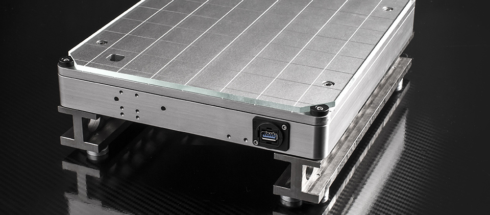
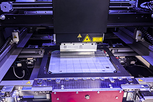
Sensor board
The central component of the measuring system is a sensor board with a rectangular measuring area of 300 x 250 mm. This is fixed on the printing table of the printer to be measured. There are different support heights depending on the type of printer. The necessary measuring electronics is connected to the sensors via a USB cable. Forces acting on the sensor surface are recorded and analysed by the CmForce software.
The sensor board allows the measurement of all common paste printers and works completely independent from the manufacturer.
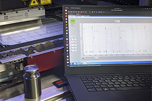
CmForce Software
The corresponding software CmForce analyses and saves the measurement results. The most important features are:
- Live display of the force-time curve
- Analysis of the force-time curve
- Consistency of squeegee force over the squeegee stroke
- Separation and comparison of the two squeegee directions (forward and reverse)
- Statistical evaluations
- Measure the squeegee force and compare with the entered values
- Analysis of the reproducibility over several prints
- Calculation of capability characteristics
- One click HTML protocol with all results
- Data export for CmCStat6.0 Expert
Procedure of a measurement
Before the first measurement a corresponding print program must be available or newly created. We recommend at least 25 measurements for each squeegee direction. The required measuring time is essentially equal to the time the printer needs for processing. After finishing the measurement, the data is analysed directly. For example, deviations from the set target value, differences between the printing directions or inconsistencies in the force distribution can be detected. It is recommended to repeat the measurement with the force levels typical in production.
At the end a protocol can be generated with one click and thus the condition of the equipment can be documented.
Customers who own a CmController with CmCStat6.0 Expert also have the possibility to export the data and analyze, document and archive them in CmCStat6.0.
Technical Specifications
- Measuring area of the sensor board: 300 x 250 mm
- Height: depending on the printing height of the printer
- Measuring range: 2 - 500 N
- Uncertainty (U): \(\pm 0.5\) N