- Determination of positioning accuracy for SMT-machines using chip components
- Impartial and independent measurement analysis complying with DIN ISO 17025
- Diagnosing root causes of misplacements and deducting the offsets correction
- Validation of the offsets correction efficiency
- Improvement of the placement quality through fine-tunings the positioning accuracy
- Calculation of \(C_m\) and \(C_{mk}\) values based on defined specifications
- Declaration of conformity according to given specifications in consideration with measurement accuracy and given target values
- Detailed und meaningful test report
- More information about measurement system

Measurement Service for Determining Positioning Accuracy on SMT Equipment
Determination of positioning accuracy for Chip placers
Preparation from CeTaQ
- CAD-Datas to create the placement program with consideration of the properties of the analysed machine like :
- Type of components
- Number of placement tools (Heads, Nozzles ...)
- Placing area
- eventually from 0°, 90°, ... to specific placing angles
- Calibrated Glass board used with the CAD-Datas
- Mobile Measurement system CmController to perform the tests
- Optionally, use of highly accurate dummy 0402 ceramic components is possible
Preparation from Customer
- Validate and finalize the placement program from the specifications defined in the CAD-Datas.
- Guarantee a good state of the analysed machine through maintenance and eventually a calibration.
- Provide the right number of nozzles necessary. The nozzles should be in good state.
- Provide the necessary number of feeder. One feeder per placement head is needed. The feeders should also be in good state to avoid any pick up errors.
- Table and access to AC power socket close to the placement machine to install the measurement system.
- Technical support to operate and program the equipment.
Placing Components on the Glass Board
The equipment to analyse is prepared with the help of technical support. The placement program loaded and components supplied. Then, the glass board is loaded into the placement equipment. The machine validate the position of the glass board with the help of fiducial marks. Finally the components are placed on the boards as defined in the placement program. The placement process is running exactly like in production. Though, the nozzle order of placement must match what was defined in the requested placement program.
Measurement of the Placed Components
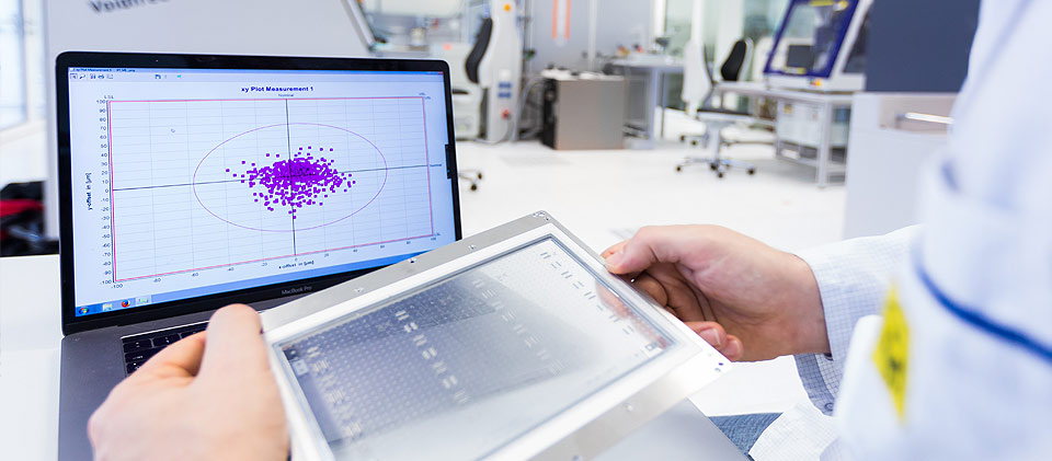
Once the glass board is populated with components, it is inserted in the CmController and the x,y positioning accuracy of the chip components will be measured. Depending on the component accuracy, the rotation angle can also be measured. The measured position is compared with the nominal position. These datas are the basis needed for further analysis.
Analysis of the Results
The measured values are used to evaluate the positioning accuracy of the equipment. In addition, numerical and graphical tools are available in the analysis software CmCStat. Beside the statement does not limit itself to a simple judgement like specifications reached or failed. Therefore, many detailed information are displayed to help in failure root cause analysis. For example, dependencies between offsets and nozzles or angles of placement are identified. This knowledge gives explanation on how the accuracy of the equipment can be improved.
Use of the Results to Optimize the Accuracy
Right after the analysis of the results, it is usually possible to optimize the accuracy of an equipment using correction offsets. In the simplest case, the advise could be for example to run a calibration using the tools provided by the manufacturer. Frequently, it's also possible to perform offsets correction directly into the machine software. Therefore, based on measured values, direct corrections can be made.
If mechanical causes are the reason for inaccurate placement, the measuring results can be used to identify the problem by ordering the sequence with groups. It facilitates the failure diagnosis for the maintenance service.
Finally, after applying the corrections, the effectiveness is verified with another measurement. According to result other measures followed from examination measurements arise from it if necessary. Depending on the results, other measurement will be done if necessary.
Report Writing
Based on the reached final condition, a test report is written at the end of the evaluation. This is written usually in our office after customer visit. Beside the detailed description of the final results, it contains the history of the necessary steps to reach the final condition.
- Measurement system and dedicated glass boards are calibrated in conformity with DIN ISO 17025
- The procedure is suitable for all type of SMT placement equipment
- The required time for a complete evaluation depends on the type of equipment. As a rule it takes between 30 minutes and 5 hours. Typically, the study takes around 2 hours.